What is Vertical Electrical Sounding (VES)?
Vertical Electrical Sounding (VES) is a geophysical resistivity method used to determine how electrical resistivity changes with depth beneath a specific point on the ground. In this method—commonly applied in groundwater exploration—a direct current (DC) is injected into the earth through two current electrodes, while the resulting potential difference (voltage) is measured between two potential electrodes.
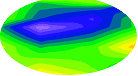
By systematically increasing the distance between the current electrodes, the electrical current penetrates deeper into the subsurface. The resulting apparent resistivity values are then plotted against electrode spacing to form a sounding curve, which reveals distinct geological layers such as topsoil, weathered zones, fractured bedrock, and fresh bedrock.
The Schlumberger Vertical Electrical Sounding method is especially popular among hydrogeologists because it combines accuracy, efficiency, and depth penetration – making it ideal for locating aquifers, estimating overburden thickness, and distinguishing between freshwater and saline layers.
Overview of the Schlumberger configuration
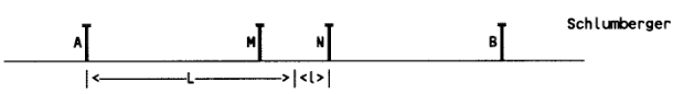
In the Schlumberger Vertical Electrical Sounding (VES) method, four electrodes are arranged along a straight line centered on the survey point. Two outer current electrodes (C₁ and C₂) inject a controlled direct current (DC) into the ground, while two inner potential electrodes (P₁ and P₂) measure the resulting voltage difference created by the subsurface’s electrical resistance.
When this arrangement is correctly established, it forms the foundation for detecting how resistivity varies with depth – a key to identifying aquifer zones and geological boundaries.
Electrode Arrangement and Geometry
The Schlumberger array is defined by two key parameters:
- AB/2 → Half the distance between the current electrodes (C₁ and C₂)
This controls the depth of investigation — larger spacing allows the current to penetrate deeper. - MN/2 → Half the distance between the potential electrodes (P₁ and P₂)
This defines the sensitivity zone near the surface where voltage is measured.
During a survey, the potential electrodes remain relatively close to the center point, while the current electrodes are moved progressively outward. This design allows the field crew to explore deeper layers without repositioning all electrodes – improving both speed and accuracy.
Pro Insight
In practice, the Schlumberger array is preferred over the Wenner configuration because it provides deeper penetration with fewer electrode movements – saving time and reducing field error.
How Depth Profiling Works
As the current electrode spacing (AB/2) increases, the electric current penetrates deeper into the subsurface. Each new spacing provides a measurement influenced by a different combination of underground layers.
By recording these readings across a range of spacings and calculating the apparent resistivity (ρₐ), the geophysicist constructs a VES curve – a visual profile that represents how resistivity changes with depth. Distinct segments of this curve correspond to different geological materials such as topsoil, clay, sand, weathered rock, or hard bedrock.